3D Designing (TinkerCad Software)
About Lesson

USING 3D TOOLS

We will see how we can use our workplane , Measuring options, Group and Ungroup feature, How hole shape is used, Aling shapes, Flip tools and Give colours to our designs,
Using the workplane
You would be surprised to know that the workplane we work can be temporarily moved. We can see in below images that blue workplane is our default plane and the orange workplane is the temporary plane. We have used this as we need some design on the angle shape, we have temporarily shifted our workplane to the angle to ease our design. It is a better option than lifting an object with the help of cone, as we don’t need to measure, we just need to place the workplane. How to use this feature? Drag the workplane from the right-side top corner and place it when you want to work.
Measuring with the Ruler
We know as normal ruler is used for giving dimensions only, but here in tinkercad a ruler is used for extra work other than giving dimensions; such as we can identify the distance of origin. In below image, the green colour measurement indicates its distance from the origin in both X-axis and Y-axis. Other three dimensions (20mm) are in X-axis, Y-axis, Z-axis, which can be changed by click on dimensions. The green mark dimension indicates the lift of the design from the workplane, currently, the 3D shape is resting on the workplane.

Grouping and Ungrouping

As we move onto the complex design, we will be combing more and more shapes together. So, this combining of shapes called grouping. Let’s take an example, as shown below three different shapes has been combined together in two of the design. It can be done with a feature called group. But notice there are design one has been a group and another is not. So, the design has the same colour is been grouped and the design having different colour is ungrouped.
The ungrouping is done by feature next to a group called as ungroup. The design in different colour indicates that shapes are not combined together.

The black Arrow shows group and ungroup icon.

Using Hole Shapes

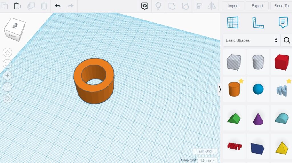
We have made lots of design using solid shapes now we will try our hand using hollow shapes or you can say hole shapes. As in the above image (i) we can see two cylindrical shapes. one is solid and the other one is semi-transparent which is a hollow shape. By this semi-transparent shape, we can make or generate holes in our design as required. The hole shape can be of any geometry as we first click on solid shape then a dialogue box appears of shape control, from where we can choose the option of a hole and make our selected design a hollow body.
Here in the second image (ii) we have reduced the size of semi-transparent cylinder and brought it to the centre of the solid cylinder, we have used group feature and combined two bodies. The hollow shaped will cut off the solid part and a hollow tube will be designed

Aligning Shapes The align tool help us to centre or position the two different shapes in a line. As with a mouse, we cannot align centre to centre of two bodies so with help of align tool we can do that. It is an important aspect in order to get correct design.We can find this option at right-hand side top corner next ungroup feature. For better understanding, we can see the images above as first image (i) show that box and cylinder are selected & is been align to centre. There is a small black dot handle as we click on the align feature, which are in three axis. We will click on these three dots for aligning our shapes. As we move our cursor on those black dot handle; we can see the preview where the alignment is going to be done. Therefore, with the help of this, we can do the alignment of shapes.
Using the Flip tool
You can create the mirror image of a shape using the flip tool. How to do this? First, select the shape and use mirror option from the top menu which is next to align feature. As we can see in the first image (i) three-axis appears. In order to flip your shape on the desired axis click onto the axis and we can get the flip shape or you can say mirror shape, and in this change of dimensions are made. In image (ii) a preview is also observed before making the selection of axis.
Color and Transparency
You can add transparency to your design for visual effect as we can see in the above images. As in the first image (i) the box is solid, it is not hollow but we have applied transparency to it, so we are able to see the small solid cylinder inside a big solid box. And in the second image (ii) the box is solid but the cylinder is hollow as we can see the outline of a hollow cylinder. This transparency can be applied by shortcut “t” which gives a visual effect or we can apply this from shape control dialogue box as we have an option for transparency given (image iii). In order to apply we need to select the transparent option.
Various colour can be given to the 3D shapes we design. Here from the shape control dialogue box, we have different colour, which can be used to make our design more attractive. Just remember if group two shapes then the whole body turns into one single colour in order to show the different shapes are now of one single body. Here in shape control dialogue box, first we need to click on solid then a bunch of colours appear from where we will give colour to our 3D designs, but grouped body we can give multicolour by selecting the multicolour option from the dialogue box shown in the above image(iii).